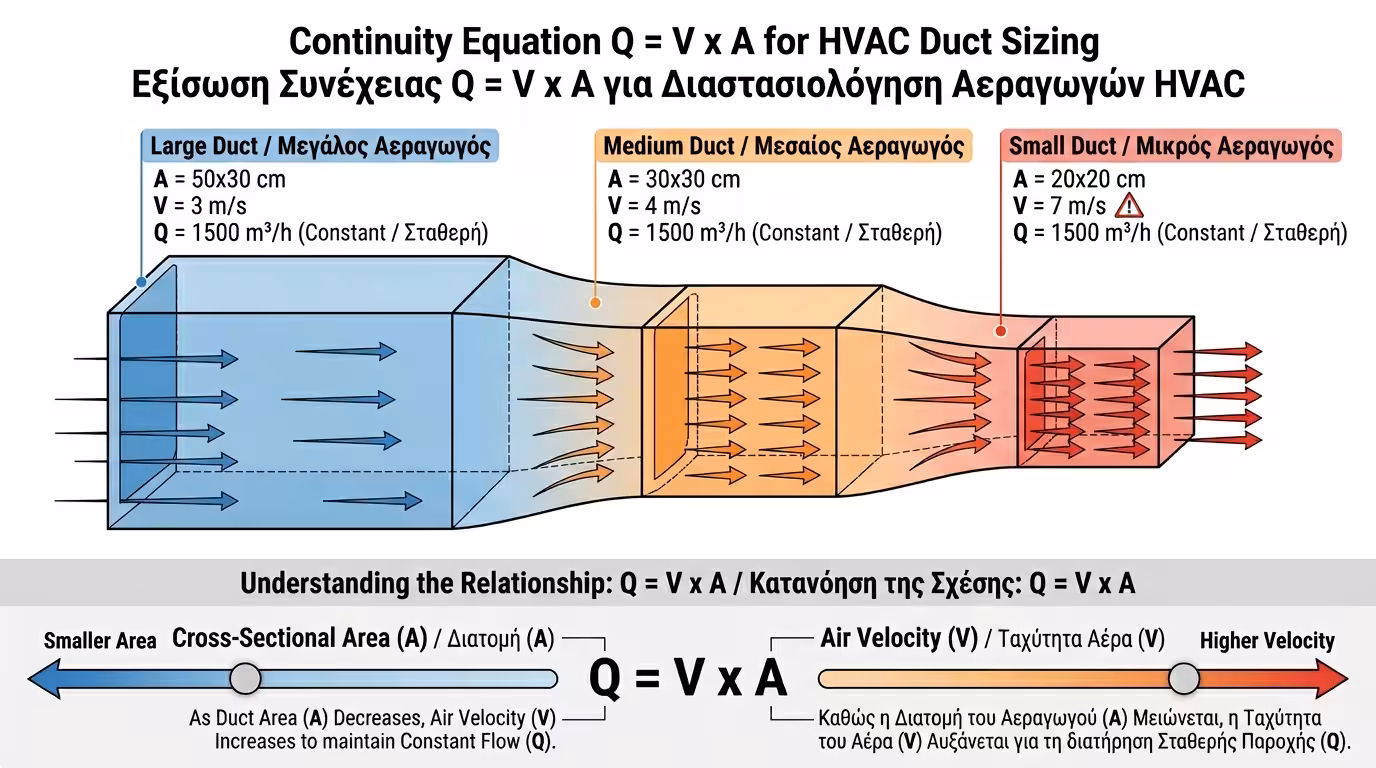
Duct Network Design: Pressure Drop, Air Velocity & Noise Control

The "heart" of any ducted air-conditioning system - a Fan Coil or VAM unit - must deliver a specific volume of air (cubic metres per hour) to every room. But if the air runs too fast, it whistles. If it runs too slowly, it never arrives.

The design engineer must balance velocity, pressure drop and duct size using fundamental laws of fluid mechanics. In this guide we explain how it all works.

1. The golden rule of aerodynamics: Q = V × A

The fundamental Continuity Equation states: Q = V × A. The required flow rate (Q) is fixed - determined by the cooling/heating loads. If we choose a small duct (small A), velocity (V) skyrockets.

Continuity equation diagram - flow rate, velocity, cross-section area

📐 Flow rate (Q)

The volume of air that must reach the room, measured in m³/h (cubic metres per hour). Calculated from thermal/cooling loads of the space - it does not change regardless of duct size. For example, a 20 m² room typically requires around 250–350 m³/h of chilled air during peak cooling.

🌬️ Velocity (V)

How fast the air travels inside the duct, in m/s. The smaller the duct, the faster the air runs - and the louder it whistles.

📏 Cross-section (A)

The cross-sectional area of the duct (how large it is). Bigger A = lower velocity = less noise. But larger dimensions mean more ceiling-void space consumed.

⚠️ Narrow duct = whistling

If the contractor installs narrow ducts to save space, velocity shoots to 7–8 m/s. Air "slams" against the walls and the room sounds like a jet engine.

2. Air velocity limits: The "noise" factor

Air velocity limits in HVAC ducts - main trunk, branches, diffuser

For a silent installation in homes or offices, engineers observe strict velocity limits during duct sizing. Exceed them and the client hears an "airport" in their bedroom.

🔵 Main trunk: 4–5 m/s

The primary duct leaving the unit carries the largest volume of air. It must be large enough to keep velocity below 4–5 m/s.

🟢 Branches: 3–4 m/s

Branch runs that turn towards individual rooms carry less air. Velocity drops to 3–4 m/s - provided the branch is sized accordingly. In hospitals or recording studios, limits drop even further to 2–3 m/s for absolute silence.

🟡 Final connection: 2–2.5 m/s

Before the diffuser, air must have "calmed down" completely: 2–2.5 m/s. This ensures air exits gently without uncomfortable drafts or whistling.

🔴 Exceeding limits = disaster

At 7–8 m/s, air becomes a "hurricane" inside the sheet metal. Noise, vibration, even diffuser blow-off are the consequences.

3. Pressure Drop: The invisible "wall" of air

As air travels through the duct it rubs against the walls (friction losses), and each time it meets an obstacle it loses energy (local losses). This is called Pressure Drop, measured in Pascals (Pa).

Duct pressure drop sources - elbows, filters, obstacles, Pascals

🔩 What causes pressure drop?

Elbows, T-pieces, reducers, air filters (especially dirty ones), flexible ducts, fire dampers - every "obstacle" steals energy from the airflow. A single unguided 90° elbow is equivalent to 3–5 metres of straight duct in friction loss.

📋 Available Static Pressure

Every Fan Coil lists a value on its dataplate, e.g. 50, 80 or 150 Pa. That is the fan's maximum "pushing force". If the ductwork exceeds it, air simply won't arrive.

❌ Failure example

A network with 10 elbows, endless flex ducts, narrow runs → pressure drop of 100 Pa. Unit rated at only 50 Pa → far rooms receive zero cooling.

🔧 Dirty filters

A clean filter creates 10–20 Pa drop. A clogged filter can push that to 50–80 Pa - "stealing" precious pressure from the fan. Regular maintenance is critical.

4. The Equal Friction Method: How engineers size ducts correctly

Proper duct sizing is never done "by eye". Engineers use special nomograms (or design software) applying the Equal Friction Method so that pressure drop per metre of duct remains constant.

Equal friction method - progressive duct reduction, uniform pressure

📏 Progressive reduction

We start with a large duct (e.g. 50×30 cm) at the unit. As we drop air at the first room, the continuing duct shrinks (30×30 cm). At the last room it ends at 20×20 cm.

⚖️ Constant drop per metre

This progressive reduction (the "reductions") maintains a constant friction loss of 0.8–1.2 Pa/m. Even the furthest diffuser receives its designed air volume. The method uses dedicated ASHRAE (American Society of Heating, Refrigerating and Air-Conditioning Engineers) nomograms or equivalent European standard calculations.

↩️ Smooth bends

Air hates sharp 90° turns. Bends must be curved (like an arc). If a 90° elbow is unavoidable, internal turning vanes (guide fins) must be installed.

📐 Proper transitions

Cross-section changes must not be abrupt like a "step". They must taper at an angle under 30° to avoid creating turbulence that wastes pressure and generates noise. An abrupt transition can triple the pressure loss compared to a smooth taper.

💡 Duct sizing is not a DIY job. If you skimp on ceiling-void space, you'll pay dearly with noise and rooms that never cool down. Proper engineering = silent living.

Related Articles

Preview