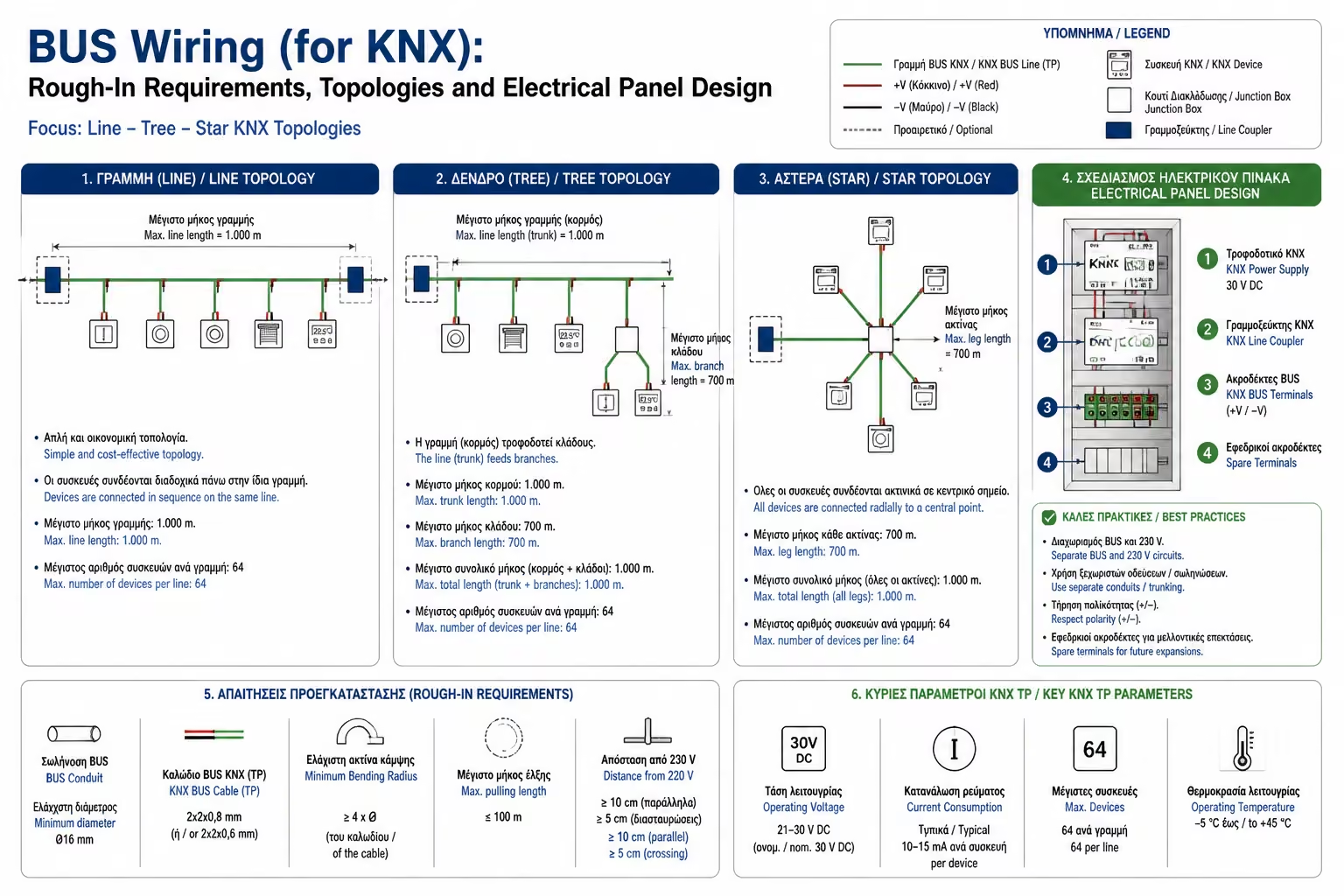
Line/Daisy Chain
The wire leaves the panel, goes to the 1st switch, from there to the 2nd, then to the thermostat, and so on.
If you are in the phase of "breaking the ground" of your new residence or preparing for a radical, ground-up renovation, you are at the most critical crossroads: Do a conventional electrical installation and later "play" with wireless systems, or build the "backbone" of a real, industrial-standard Smart Home?
As we have seen, the global KNX standard is the undisputed king of reliability. But KNX is not something you can decide after the walls are plastered. It requires a completely different wiring philosophy that separates "power" from "mind".
As engineers, let's take a look at how you should guide your electrician installer through the foundation stage, what the famous "green wire" is, and why your electrical panel will now look like a server closet.
In a conventional house, the power cables (230V) go from the panel to the wall switch, and from the switch to the lamp. That is, the switch "lifts" the burden of the current.
In a KNX home, the philosophy is completely reversed. There are two completely separate networks:
When you press the switch in the living room, you do not close a 230V circuit. You simply send a digital "message" (a telegram) over the BUS cable to the board, telling the brain: "Power up the living room lamp."
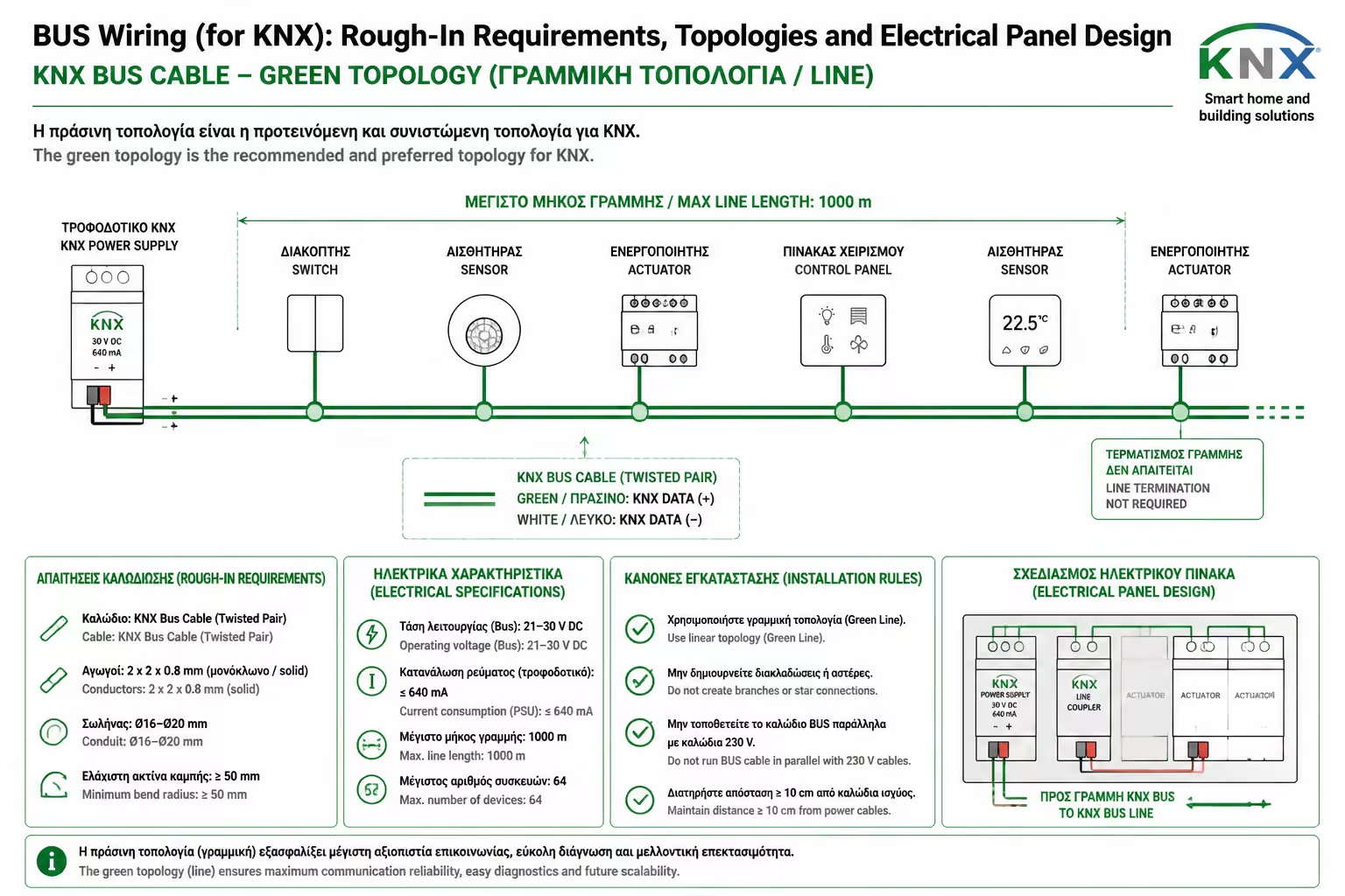
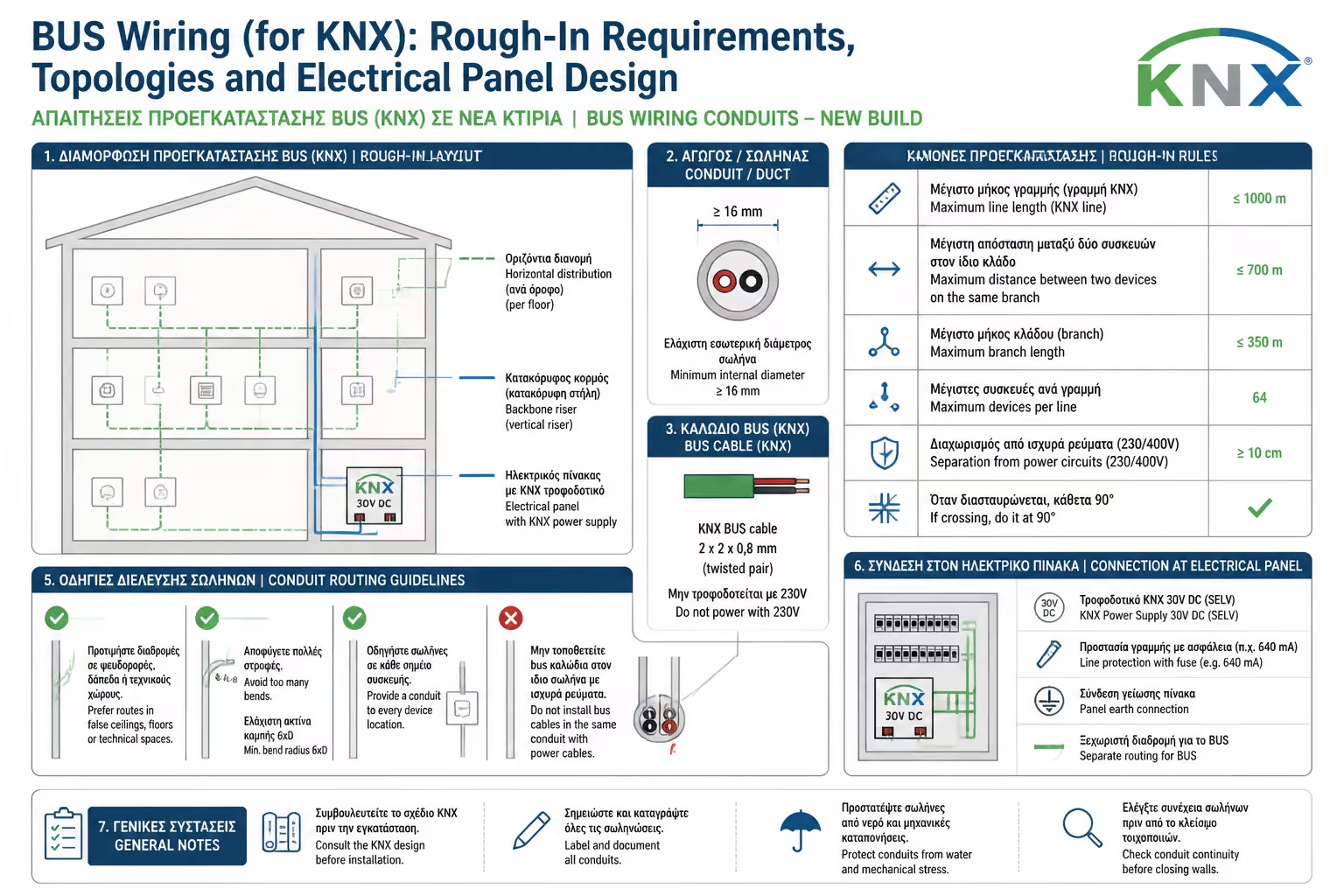
The trademark of KNX is the shielded, green BUS cable (type J-Y(St)Y 2x2x0.8).
KNX is extremely flexible in how the electrician will run the green wire through the coils. Three basic topologies are allowed:
THE ONLY UNBREAKABLE RULE: Creating a Ring is strictly prohibited. The beginning of the cable must never meet its end. If a loop is created, the digital telegrams will "cycle" until the entire network collapses.
The wire leaves the panel, goes to the 1st switch, from there to the 2nd, then to the thermostat, and so on.
Each switch has its own cable that terminates separately at the main panel.
A combination of the above. The cable leaves the panel, goes to a junction box and from there "opens" like branches to different rooms.
This is where builders and architects make the biggest mistake, underestimating space.
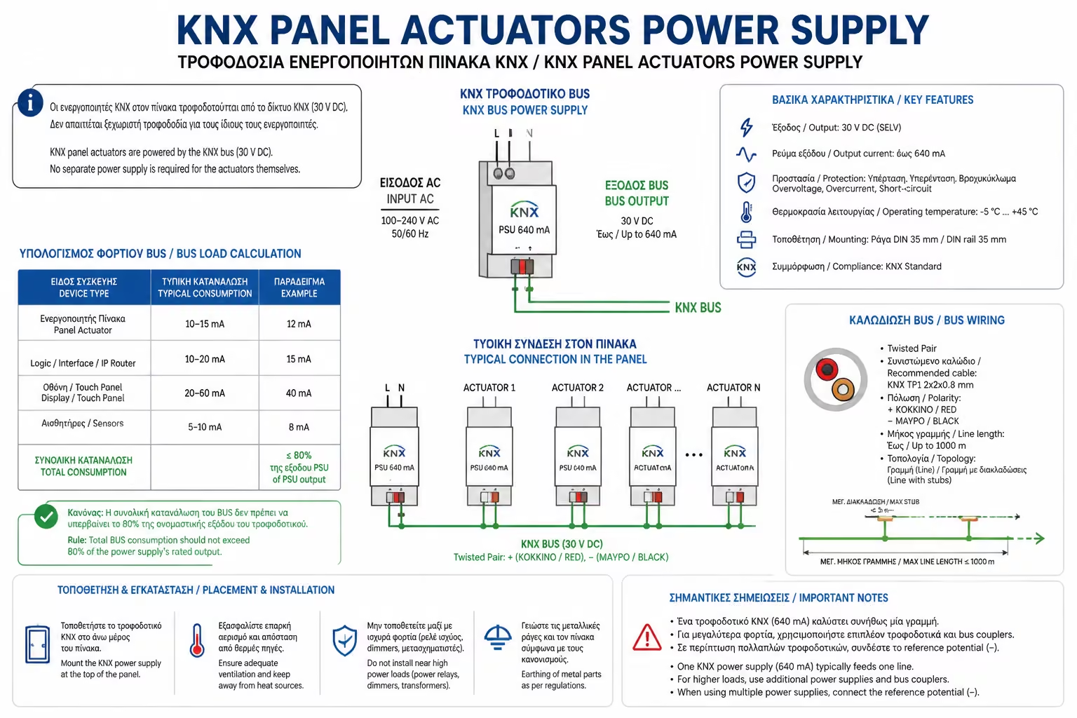
In KNX, because the wall switches do not control the loads, this work is done inside the panel. The KNX panel must be up to 3 times larger than a conventional panel!
What goes inside this huge board: 1. Fuses & Leakage Relays: As in any home. 2. The KNX Power Supply (PSU): The "heart" of the system that produces the 29V DC to give life to the green wire. It has a special coil (choke) to separate the data from the current. 3. Actuators: These are the "muscles". They are large devices that fit into the DIN rails of the panel and listen to the BUS commands. There are: Switch Actuators (Relays) to turn lights and sockets on/off. Dimming Actuators to increase or decrease the intensity of the lighting. Blind/Shutter Actuators* that control the motors of the blinds and awnings. 4. Ventilation Space (Cooling): Because the board houses dozens of electronic boards (Actuators), it develops temperature. The designer should leave 20-30% empty space between the components (or provide for active ventilation) so that the materials do not burn.
KNX cabling (BUS) is the definitive answer to the question of building automation reliability. It does require careful planning, plenty of space for central panels, and more meters of power cords (since each light bulb runs on the panel), but the payoff pays off: You get a home where the switches don't carry dangerous currents, they can be reprogrammed to do anything you want at any time, and the infrastructure (the green wire) will withstand whatever technological upgrades the next few decades bring.
Next Step: We have completed the presentation of the protocols, either wireless (Zigbee, Z-Wave, Matter) or wired (KNX). Before we move on to the "Hardware" of Class B smart switches, there is one last, "sacred" rule of the modern Smart Home that we must establish.
Return to category.
Go to categoryReturn to the central guide.
Go to guide