🔧 Operating principle
The engineer measures the differential pressure (ΔP) across the valve's two test points. Using the Kv curve, they set the turns so flow drops to the design lt/h.
In small houses, balancing is done with an Allen key on the lockshield. But in hotels, hospitals or apartment blocks with hundreds of fan coil units and variable demand, that method collapses entirely.
Enter balancing valves - static and dynamic - and the modern PICV that combines control, balancing and isolation in a single body.
A static balancing valve (e.g. IMI Hydronic TA-STAD) is essentially a fixed throttle: set once during commissioning and never adjusted again.
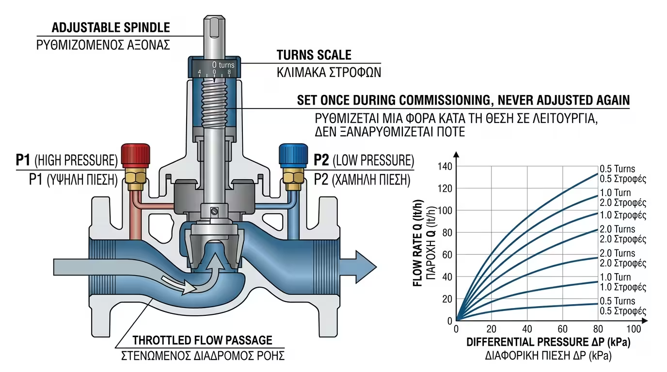
The engineer measures the differential pressure (ΔP) across the valve's two test points. Using the Kv curve, they set the turns so flow drops to the design lt/h.
Every valve has two colour-coded plugs (P1, P2) for connecting a digital manometer. The technician reads actual kPa, then converts to lt/h via the Kv table.
In constant-flow networks (e.g. an underfloor zone where the circulator always runs at the same speed), a static valve works perfectly - cheap and reliable.
In variable-flow networks (VRF, fan coils opening and closing), pressure changes constantly. The static valve cannot react - balancing is lost.
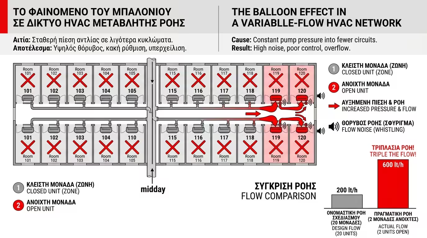
Imagine 20 fan coil units on a hotel floor. At midday, 18 close (no cooling needed). The same circulator pressure now pushes into just 2 units - their flow rockets to triple the design value.
When enough valves close in the network, pressure surges in the open circuits. Units demanding cooling get flooded with excessive flow, while those just opening see enormous ΔP.
Flooded fan coils blow freezing air (overcooling), while those at the network end crawl. Automation fights with thermostatic valves, but the root cause remains unsolved.
Excessive flow through fan coils creates flow noise (whistling, rattling). The circulator consumes extra electricity for no reason - pure energy waste.
Dynamic balancing: valves that react automatically to pressure changes, maintaining constant flow regardless of what neighbouring units are doing. This is the PICV.
The Pressure Independent Control Valve (PICV) is the pinnacle of development. It integrates in a single body: control valve, automatic balancing and isolation valve. Three components in one.
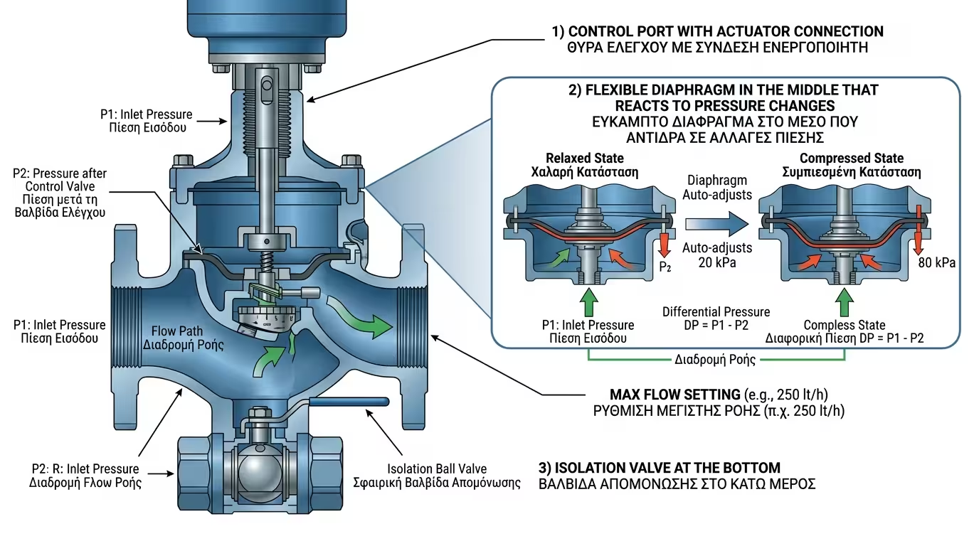
Inside the body sits a flexible diaphragm that reacts to pressure changes. If ΔP increases (a neighbour closed), the diaphragm partially closes, automatically reducing flow to the target value.
Flow remains constant - e.g. 200 lt/h ± 5% - even if ΔP jumps from 20 kPa to 80 kPa. The network "doesn't know" anything changed. Zero Balloon Effect, zero interference.
The technician turns a rotary scale on the PICV to set maximum flow (e.g. 250 lt/h). The actuator can then modulate 0-100% of that flow during operation.
Hospitals, 4-5 star hotels, data centres, universities. Any point with variable flow and a requirement for zone independence is a PICV candidate.
A PICV costs 3-5 times more than a static valve. But in variable-flow networks, payback comes within 2-3 years thanks to circulator energy savings.
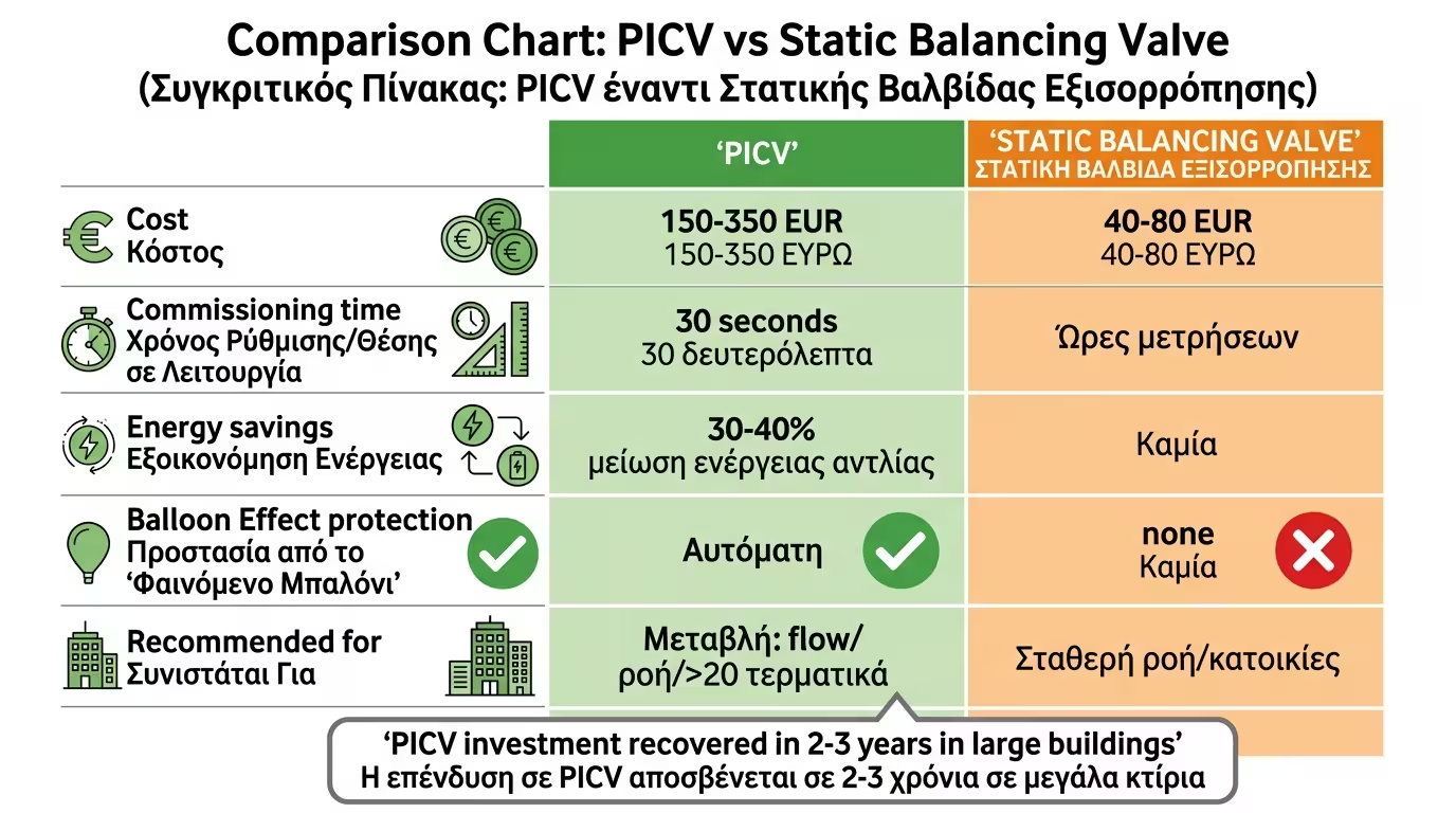
A ½" static valve costs €40-80. A ½" PICV costs €150-350. In a building with 200 fan coils, the difference reaches €40,000-60,000.
Without PICVs the circulator "fights" against imbalance, consuming 30-40% more electricity. After PICV installation, the inverter circulator reduces speed - saving thousands of kWh annually.
In a house with 5 radiators, PICVs aren't needed. A lockshield valve + rotameters suffice. PICVs are only justified in networks with >20 terminals and variable demand.
Static valves require hours of measurement during commissioning. A PICV is set in 30 seconds (turn the scale) - saving days of engineer time on large buildings.
💡 In large variable-flow networks, the PICV is not a luxury - it's a necessity. Without them, no BMS or inverter can compensate for uncontrolled pressure fluctuations.
Return to category.
Go to categoryReturn to the central guide.
Go to guide