🗺️ A real map of daily use
The drawing shows the interaction between outlets, lights and furniture, so it is not just a technical document but a practical guide to how each room will function once you move in.
Everyone knows the excitement of holding the architectural drawings for a new home or renovation, yet the electrical floor plan often turns that excitement into confusion the moment the lines, circles and symbols appear.
The key point is simple: changes on paper cost nothing, while changes after plastering can cost hundreds of euros, so learning to read the drawing properly is the safest way to correct mistakes before the installation becomes expensive and messy.
An electrical floor plan is the map of your house viewed from above, usually at 1:50 scale, and it shows exactly where every electrical element will be placed inside the property.
Unlike the single-line diagram, which mainly serves the electrician and describes the protective devices inside the board, the floor plan matters directly to the owner because it connects lighting points, switches and outlets to the way the home will actually be used.
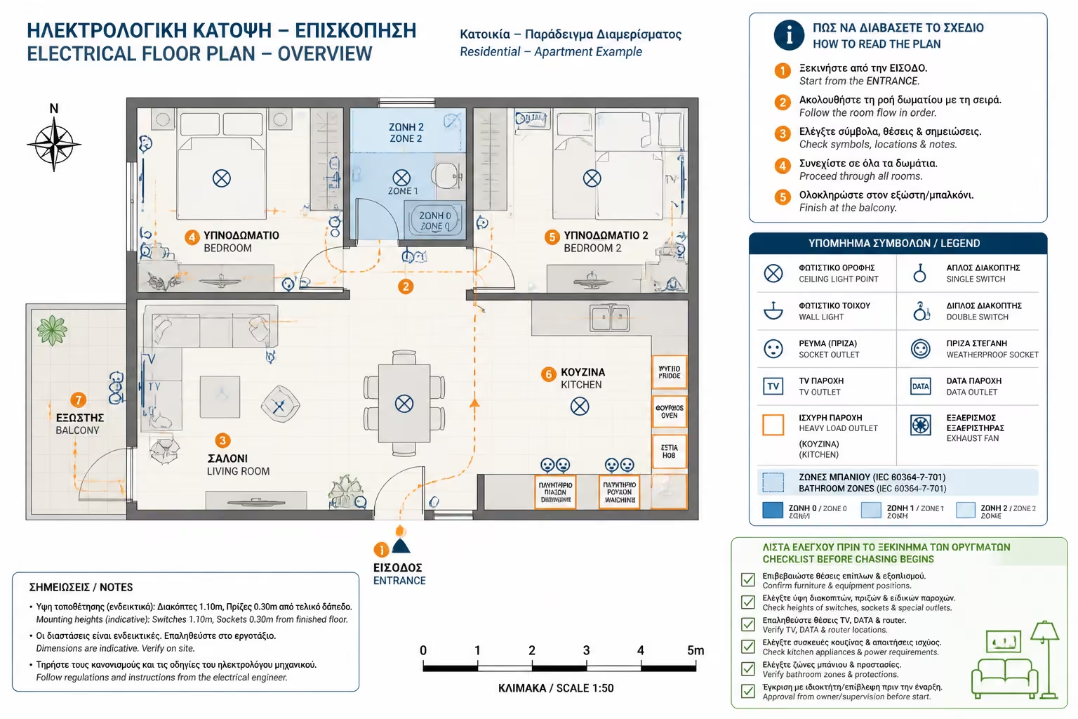
The drawing shows the interaction between outlets, lights and furniture, so it is not just a technical document but a practical guide to how each room will function once you move in.
The single-line diagram explains the board and protections, while the floor plan is about positions, heights and user access, which are the things you must review before construction starts.
If the bed shifts 50 centimetres on the architectural drawing, the bedside switch may end up hidden behind the headboard, so early checking saves costly remedial work after chasing and plastering.
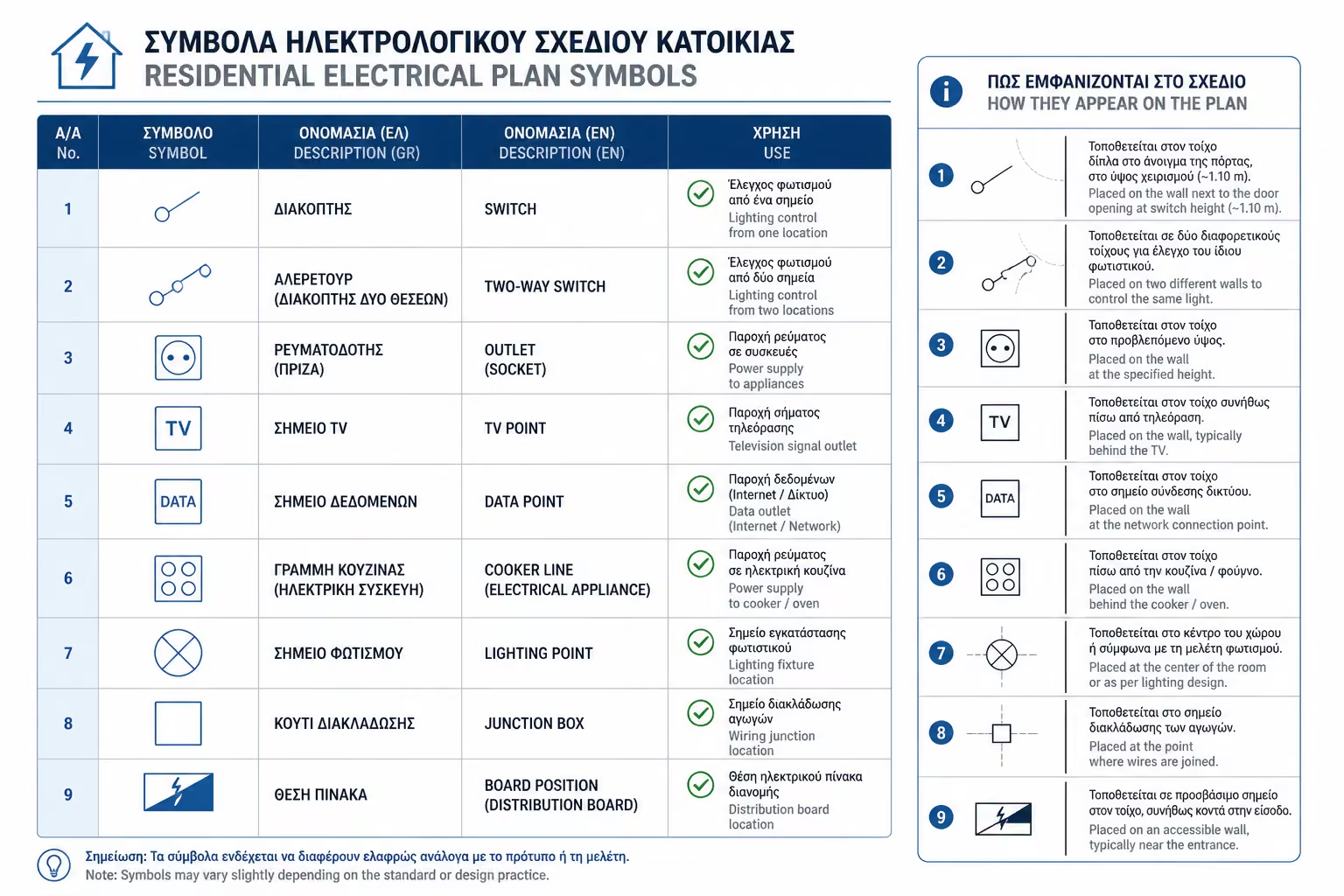
To read a plan correctly, you first need to understand its alphabet. Different software packages may vary slightly, but Greek and European practice follows the same basic symbolic logic.
The main electrical board is usually shown as a rectangle with a diagonal line or shaded mark and represents the point from which all circuits start, while the meter is often marked as M or Wh near the entrance or site boundary.
A standard ceiling light is commonly a circle with a cross, a wall light is a similar symbol tied to the wall, spotlights are smaller solid circles, and concealed LED lighting often appears as a dashed line along a plasterboard recess.
A simple switch is a small circle with one projection, a two-gang control has two projections, and two-way switching is shown with a distinct symbol or A/R note, allowing the light to be switched from both ends of a corridor or bedroom arrangement.
A Schuko outlet is typically shown as a semicircle with a central line, double and triple outlets add extra marks or x2 and x3 notation, high-load appliance outlets use additional indication, and weatherproof sockets are specially marked.
TV points, RJ45 data outlets and alarm devices such as PIR sensors and magnetic contacts must be clearly separated from power circuits, because keeping strong and weak current systems apart is a basic rule for avoiding interference.
The lines connecting the symbols show how conduits and cables travel through the building, so without reading them properly you cannot understand how the installation has really been planned.
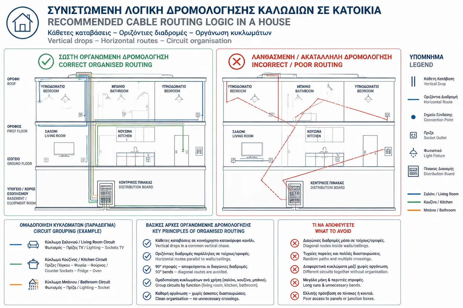
A solid line usually indicates wiring running inside the wall or inside the concrete slab, which is the standard concealed route through the structure.
A dashed line often means wiring hidden under the floor or inside a suspended ceiling, so it typically represents a different routing strategy from the vertical wall drops.
Codes such as 3x2.5mm² mean three conductors - phase, neutral and earth - each with a cross-section of 2.5 square millimetres, which is the standard arrangement for a socket circuit.
When reviewing the drawing, take mental walks through the house as if you were waking up, making coffee or sitting on the sofa, because that is the fastest way to spot real-life usability mistakes before any chasing begins.

Check the opening arc of each door on the architectural plan. If the leaf hides the switch, the room will be awkward from day one. The switch should always sit on the opening side of the door, not behind it.
If there is no two-way switch by the bedside table, you will have to get out of bed every night to turn off the central light, which is one of the most common ergonomic failures in a new home.
A TV wall needs much more than two outlets because a television, router, decoder, sound system and console usually require at least five or six Schuko points. If the drawing shows only two, extension strips are inevitable.
In Greek construction the initial plan acts as the guide, but small changes almost always happen on site while walls are built and conduits are installed.
At the end of the project, the licensed electrician issues the official installation declaration to DEDDIE together with the final as-built single-line diagram and floor plan, documenting the real positions of the materials and giving you legal and insurance protection.
💡 Now that you can read the drawing, the next key step is deciding exactly where those symbols should be placed and at what height in real daily use.
Return to category.
Go to categoryReturn to the central guide.
Go to guide