
Current Transformers (CT Clamps): How to measure current safely, without cutting or disconnecting the central wires

In the previous articles, we discussed consumption meters through which the current passes directly. But what happens when you want to measure the main conductor of an entire house or a large industrial motor?

There, the current can reach 60, 100 or even 200 Amperes. The wires are as thick as your thumb. If you try to cut that wire to run it through a small, plastic device, you'll likely melt the device, start a fire, or (at best) lose power.

The solution is one of the safest and most elegant components in electrical measurement: the current transformer, or CT clamp. It is a small clip that reads the current through the cable insulation without touching the copper conductor itself. Let's see how that works.

1. The Physics behind Magic (Electromagnetic Induction)

The operation of the CT Clamp is based on a fundamental law of electromagnetism (Ampère/Faraday's Law):

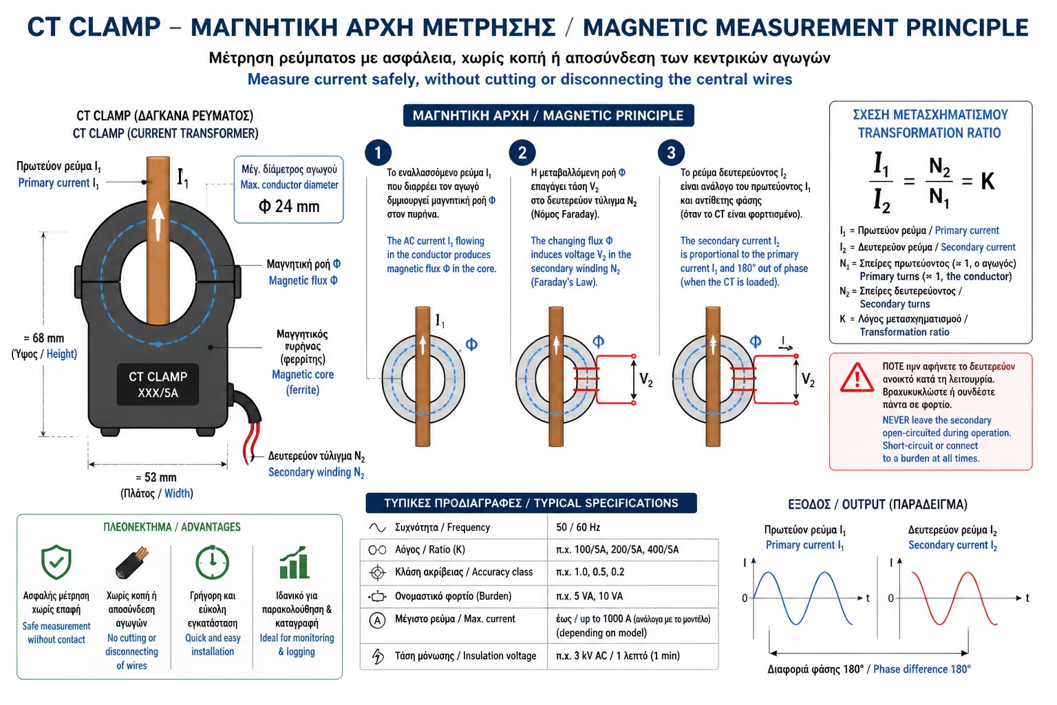
When alternating current passes through a wire, it creates an invisible, pulsating magnetic field around the wire. The more current that passes (eg when you turn on the oven), the "stronger" this magnetic field outside the plastic sheath of the wire becomes.

The CT Clamp is essentially a ring (made of a special magnetic material) wrapped with hundreds of turns of ultra-fine copper.

  • When you clip the CT clamp around the main conductor, that magnetic field is captured inside the ring.
  • This field creates (induces) a new, tiny and completely safe current in its own thin wire, which travels to your smart meter (eg Shelly).
  • The meter reads this "mini" current and calculates mathematically what the actual current is in the main wire.
Illustration for 1. The Physics behind Magic (Electromagnetic Induction)

2. Pros: Why Electricians Love Them

Illustration for 2. Pros: Why Electricians Love Them

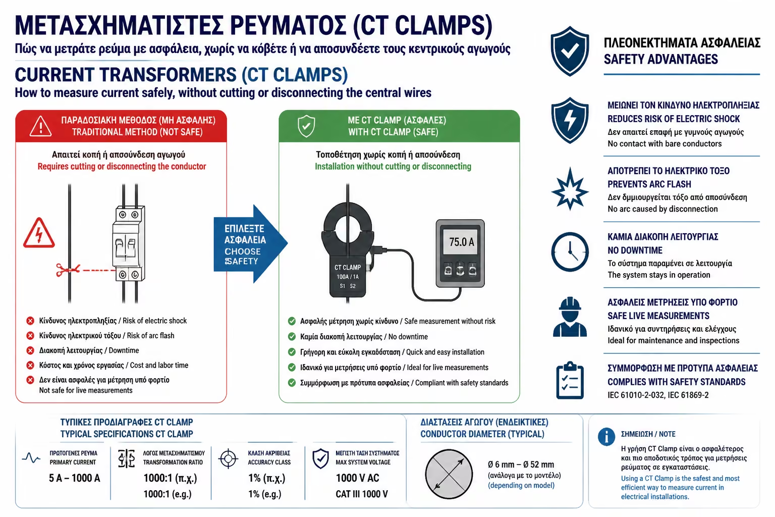
Indirect measurement with CT Clamps has almost completely eliminated direct meters in large installations, for 3 very simple reasons:

  1. Absolute Safety: No need to unscrew or cut any high voltage cables. The CT "hugs" the wire over its insulation.
  2. Zero Downtime: If you want to put a meter in a supermarket fridge or a company's server, you don't need to "take down" the general to do the wiring. You simply clip the clamp around the cable while in operation.
  3. Thermal Protection: Even if there is a short circuit in the house and the power surges, the heavy load does not pass through your meter board (so it will not burn it). It only goes through the thick wire.

3. Installation in practice: The 3 fatal mistakes of amateurs

Installing a CT clamp looks deceptively simple, but it has important pitfalls. As always, the electrical panel should only be opened by a licensed electrician.

If you decide to read the measurements and see "0 Watt" or "negative" consumption, check the following 3 points:

Illustration for 3. Installation in practice: The 3 fatal mistakes of amateurs

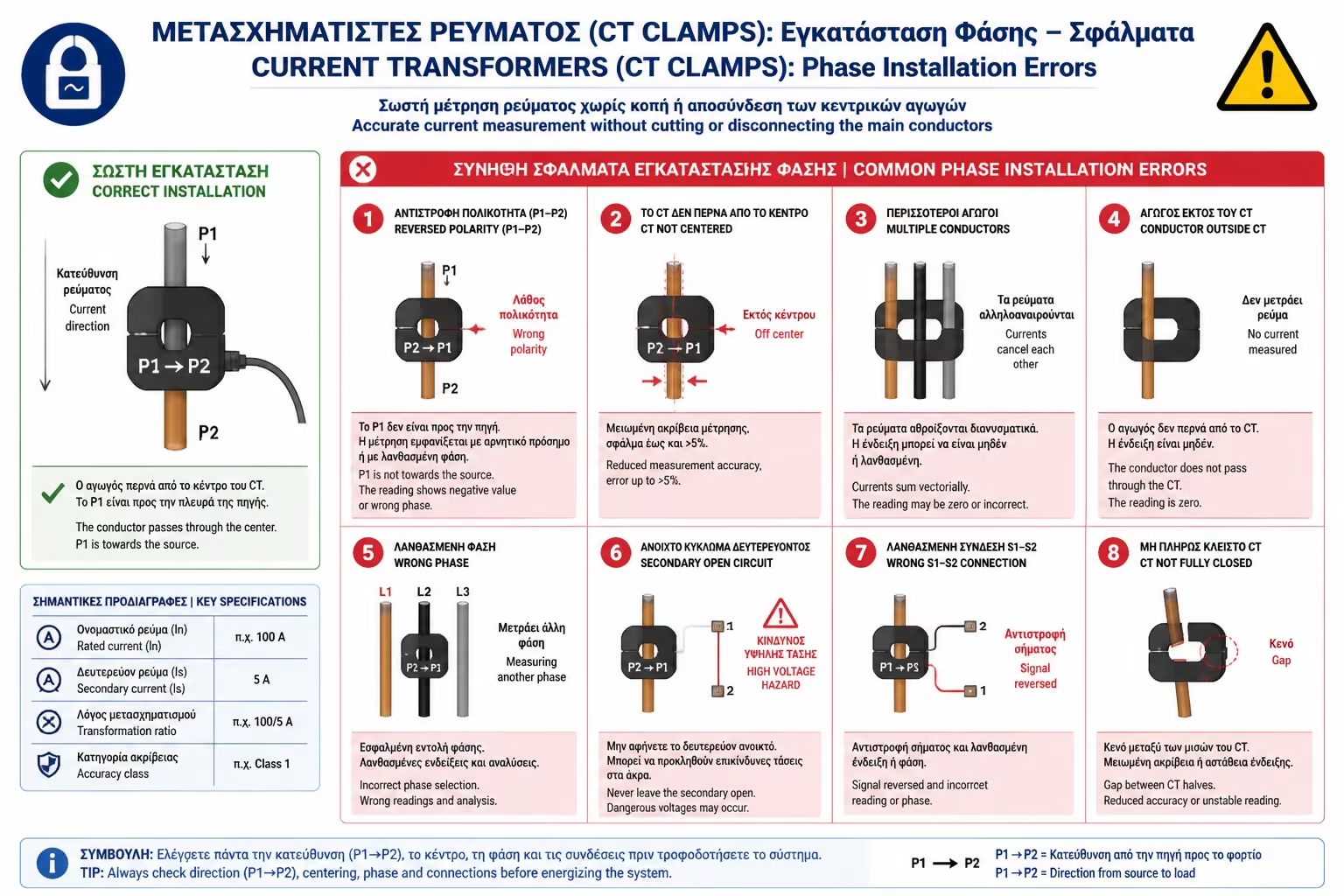
Mistake 1st: "Hug" both wires (Live + Neutral)

This is the most classic mistake. Many people take the thick cable of a device (eg TV) and put the clamp around the whole cable. What happens: Current "goes" through the Phase and "returns" through the Neutral. Their two magnetic fields are completely opposite. If the clamp catches both at the same time, the fields cancel each other out and your meter will always read 0 Amps. The Right Fit: The CT Clamp must clamp ONLY ONE WIRE (usually the brown/black Phase wire).
Mistake 2: Wrong Direction (Negative Count)

There is always an arrow marked on the CT clamp body, and direction matters. The arrow should point toward the load and away from the source. If the clamp is installed in reverse, the meter may interpret the current as flowing backward and show negative power. In PV applications, two CT clamps may be needed to distinguish consumption from production or export to the grid.

Mistake 3: "Peg" did not close well

In order for the magnetic core to work, the two jaws of the clip must "kiss" perfectly. If there's even a millimeter of gap (eg because a bit of the cable's insulating plastic got caught in between), the magnetic circuit breaks and your readings will be completely wrong (way below reality). Make sure you hear the characteristic "click" when you close it.

4. The Transformation Ratio (Ratio)

Illustration for 4. The Transformation Ratio (Ratio)

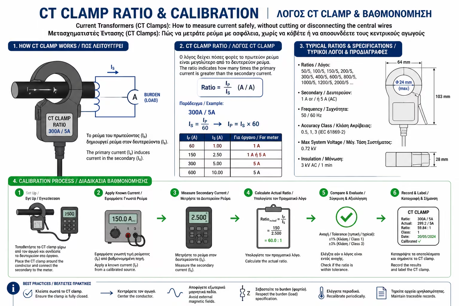
If you buy a standalone current transformer for an industrial panel, you may see ratings such as 100/5A or 50A/50mA. This is the transformation ratio. A 100/5A CT means that when 100 amperes flow in the main conductor, the CT delivers 5 amperes to the meter. After installation, the electrician must enter that ratio into the meter settings so the software calculates the true current correctly. On many residential smart meters, the CT clamps are sold as matched accessories and are already calibrated.

Summarizing

CT Clamps are the "stethoscopes" of the electrician. They allow accurate, safe and non-invasive energy measurement, saving us from short-circuit risks and complex wiring. Just make sure they only "bite" the Phase and that their arrow is pointing in the right direction.

Next Step: Everything we've said so far has been about a simple, "single-phase" house. But what if your panel is large, has 3 central fuses and 3 phase power? How does the measurement change there? We continue with the next guide in the category: Single phase vs. Three-Phase Consumption Meters: What to look out for before buying and how the phases are connected.

Related Articles

Preview