
A multimeter is not enough
It is not designed to measure true earth resistance in the soil.
The mere existence of strip, rods or a plate in the ground proves nothing by itself. An earthing system becomes meaningful only when it is measured and shown, in numbers, to offer a low and stable path for current into the ground.
That is why the earth tester is effectively the diagnostic instrument of the earthing system. It is not enough to assume that 'some kind of earth exists'. You need method, isolation of the electrode and a result in ohms that can be interpreted correctly.
It is equally important to understand that there is no single target number without context. Acceptable values depend on the supply system, the presence of RCD protection, lightning-protection needs and the nature of the building itself.
In practice, the guide "Earth Resistance Measurement: How It Is Done, What an Earth Tester Is and Which Values Are Acceptable" is not just theory. It works as a checklist for supervisors, owners and installers who want to verify that the chosen solution on site is genuinely safe, measurable and compatible with the wider protection architecture of the building.
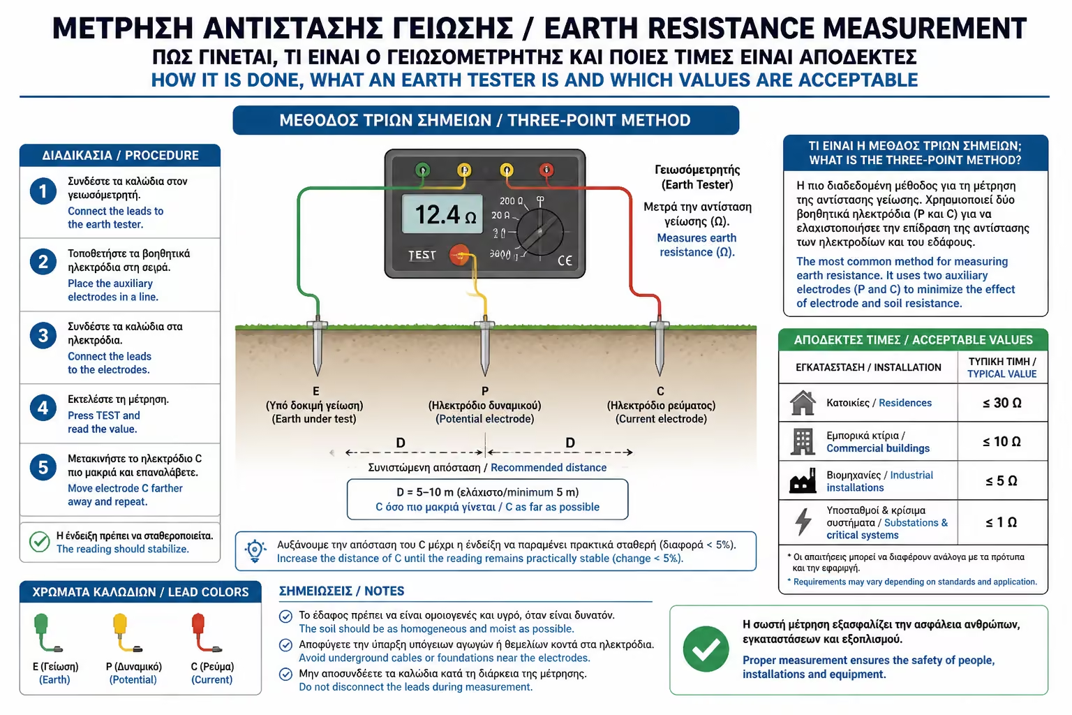
A multimeter, a lamp test or improvised socket tricks do not measure earthing in a technically acceptable way. The earth tester injects controlled test current and evaluates the electrode properly instead of relying on crude voltage indications.
That matters because earthing is judged by actual resistance, not visual confidence. If the tool is wrong, even a pleasant-looking number means very little.
Within the topic "Earth Resistance Measurement: How It Is Done, What an Earth Tester Is and Which Values Are Acceptable", the section "1. The earth tester is the only serious tool for the job" is more than background information. It is a control point that determines whether the study, the site execution and the future maintenance of the work remain technically coherent and operationally reliable over time.
It is not designed to measure true earth resistance in the soil.
Owning an earth tester is not the same as using it correctly.
A proper value can be documented and reproduced later.
The measurement record is part of the handover of the work.
Before measurement, the electrode should be disconnected from the building so that parallel metallic paths are not included in the reading. Auxiliary probes are then placed at suitable distances and the tester applies the classic fall-of-potential or 62 percent method.
If distances are wrong or the system is not isolated, the reading may look impressively low while failing to reflect reality. Accuracy here is a matter of method, not luck.
Within the topic "Earth Resistance Measurement: How It Is Done, What an Earth Tester Is and Which Values Are Acceptable", the section "2. The three-point method requires isolation and correct geometry" is more than background information. It is a control point that determines whether the study, the site execution and the future maintenance of the work remain technically coherent and operationally reliable over time.
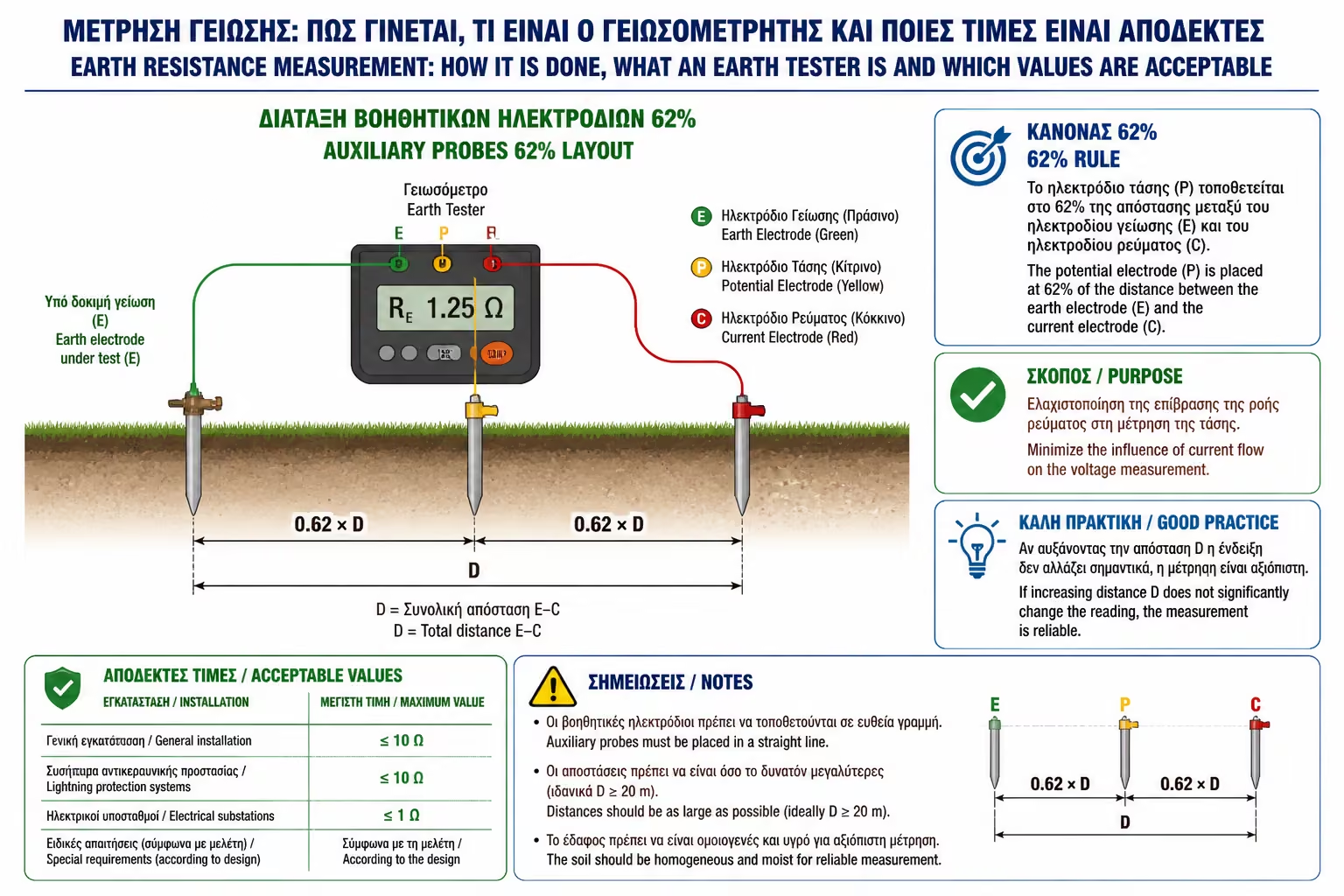
Otherwise foreign metallic paths influence the result.
Correct spacing is part of the reliability of the test.
Poor layout produces false confidence.
Even a good earth can appear bad, or the reverse, if the method is careless.
In residential TT systems with RCD protection, the aim is usually a comfortably low value that remains credible even when seasonal moisture changes. In sites with lightning protection or more demanding technical requirements, the targets become stricter.
The key trap is to treat a barely acceptable reading as a reason for complacency. Good engineering practice does not seek only the minimum pass threshold but a margin that survives time, drought and ageing.
Within the topic "Earth Resistance Measurement: How It Is Done, What an Earth Tester Is and Which Values Are Acceptable", the section "3. Acceptable values depend on the system and the use" is more than background information. It is a control point that determines whether the study, the site execution and the future maintenance of the work remain technically coherent and operationally reliable over time.
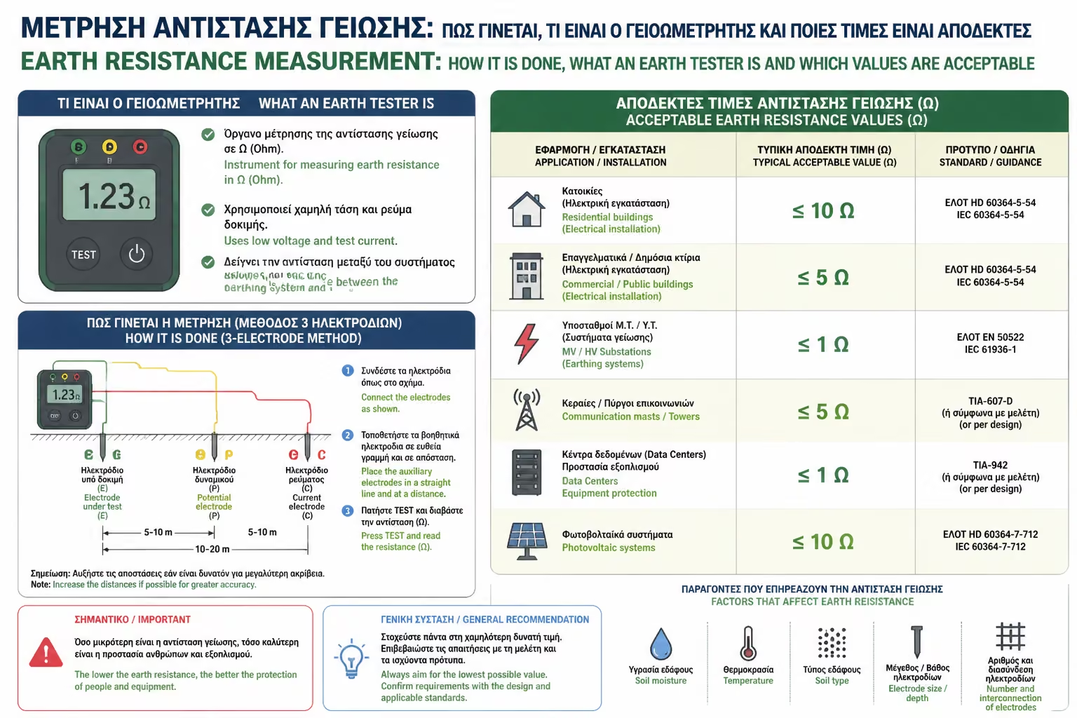
Interpretation changes with TT, TN, RCD strategy and building use.
A winter value may worsen noticeably in summer.
Low resistance becomes even more important where surge energy must be dissipated.
We want safe performance for years, not just on test day.
If the resistance is high, the proper response is technical intervention: more rods, greater depth, an array, a plate or soil-improvement material where appropriate. The measurement tells us what to fix, not what to hide.
The earth system should then be retested periodically. Corrosion, soil changes and site works can all change performance. Earthing is not installed and forgotten; it is monitored over time.
Within the topic "Earth Resistance Measurement: How It Is Done, What an Earth Tester Is and Which Values Are Acceptable", the section "4. A poor result means improving the electrode, not decorating the paperwork" is more than background information. It is a control point that determines whether the study, the site execution and the future maintenance of the work remain technically coherent and operationally reliable over time.
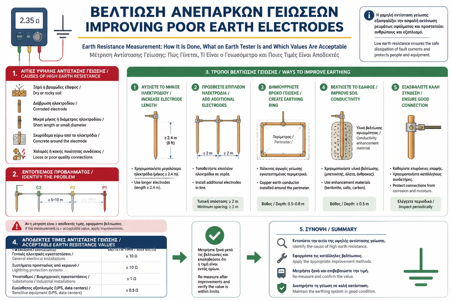
The answer is system improvement, not creative interpretation.
Increasing the effective electrode usually lowers the reading meaningfully.
An old report is not a lifetime guarantee.
It captures the state of the installation at a specific moment and should be renewed.
Return to category.
Go to categoryReturn to the central guide.
Go to guide